I never owned an Amiga when they first came out, being a Spectrum kid and then the BBC B, but I admit to being tempted by the advanced games, graphics and sound that they offered. Having recently acquired 2 Amiga’s and modifying them with FlashFloppy drives I got down to some serious game playing…. only to realise that most game need 1MB of RAM. This wasn’t too much of an issue as a ‘trap door’ expansion card came with one of the machines. But I also noticed that one of the machines had motherboard sockets for the memory upgrade.
Type of RAM on an Amiga
The Amiga has three types of RAM that can be configured;
- Chip RAM – used by the custom chips for graphics and sound
- Fast RAM – used by the CPU for speed
- Slow RAM – uses a shared bus – and the default for the ‘trap door’ expansion
Now, I have no idea how much of an issue this is but I decided that I needed fast RAM as it sounded….. fast.. 😉 and that I would add it to the motherboard to keep the expansion card for the other machine.
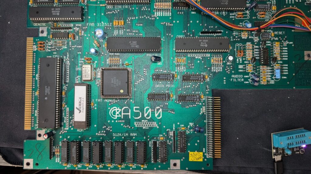
Upgrading a version 6a motherboard
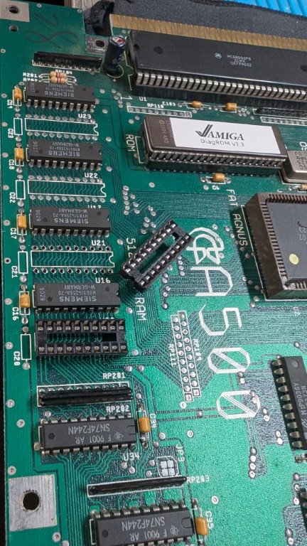
The first job was to solder sockets into the spare ram locations. This was a quick and easy job, followed by inserting the new 514256 (4 bit 256K memory) chips. Before fitting I tested each in my memory tester as they were purchased from AliExpress.
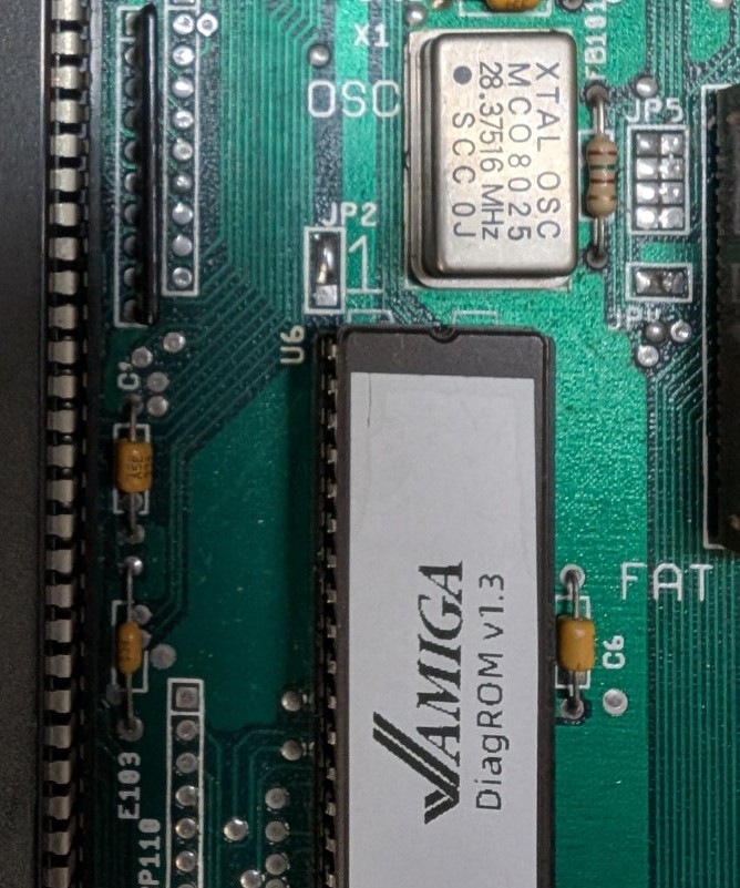
Booting the machine with the diagnostics ROM didn’t show any change in the amount of memory, but at least I hadn’t broken anything.
To enable the new memory there are two jumpers, which are poorly documented, that need to be configured when adding memory chips to the motherboard – the trapdoor worked without any jumper changes.
Setting up the jumpers
The first jumper, JP2, is located above the RAM and to the right of the CPU. This controls where the expansion ram maps in the memory map – either CHIP or Slow RAM (default) – we want Chip ram.
To set this the middle and top pads need to be connected, by default the middle and bottom pads are connected so this link needs to be cut.
I cut the link between the bottom and middle pads with a craft knife and joined the middle and top with solder.
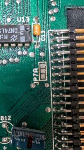
Next Jumper 7A needs to be configured, which is located to the left of the expansion connector. By default the middle and bottom pads are connected, which enables the expansion ram card – this needs to be cut. The top pad is ground and the documentation is – confusing – to say the least. I found that connecting this to the middle pad refused to enable the onboard RAM and leaving the middle pad disconnected enabled the new RAM ?
So the final configuration that works for my Amiga 500 is
- JP2 – middle and top pads connected
- JP 7A – no pads connected
And there you have it – now my Amiga has 1MB of fast onboard RAM – verified using the DiagROM.